What Digital Fabrication Makes Possible
How a garden studio in the North Wessex Downs was designed and built from 141 machine-cut parts, and why the same approach suits small buildings of all kinds.
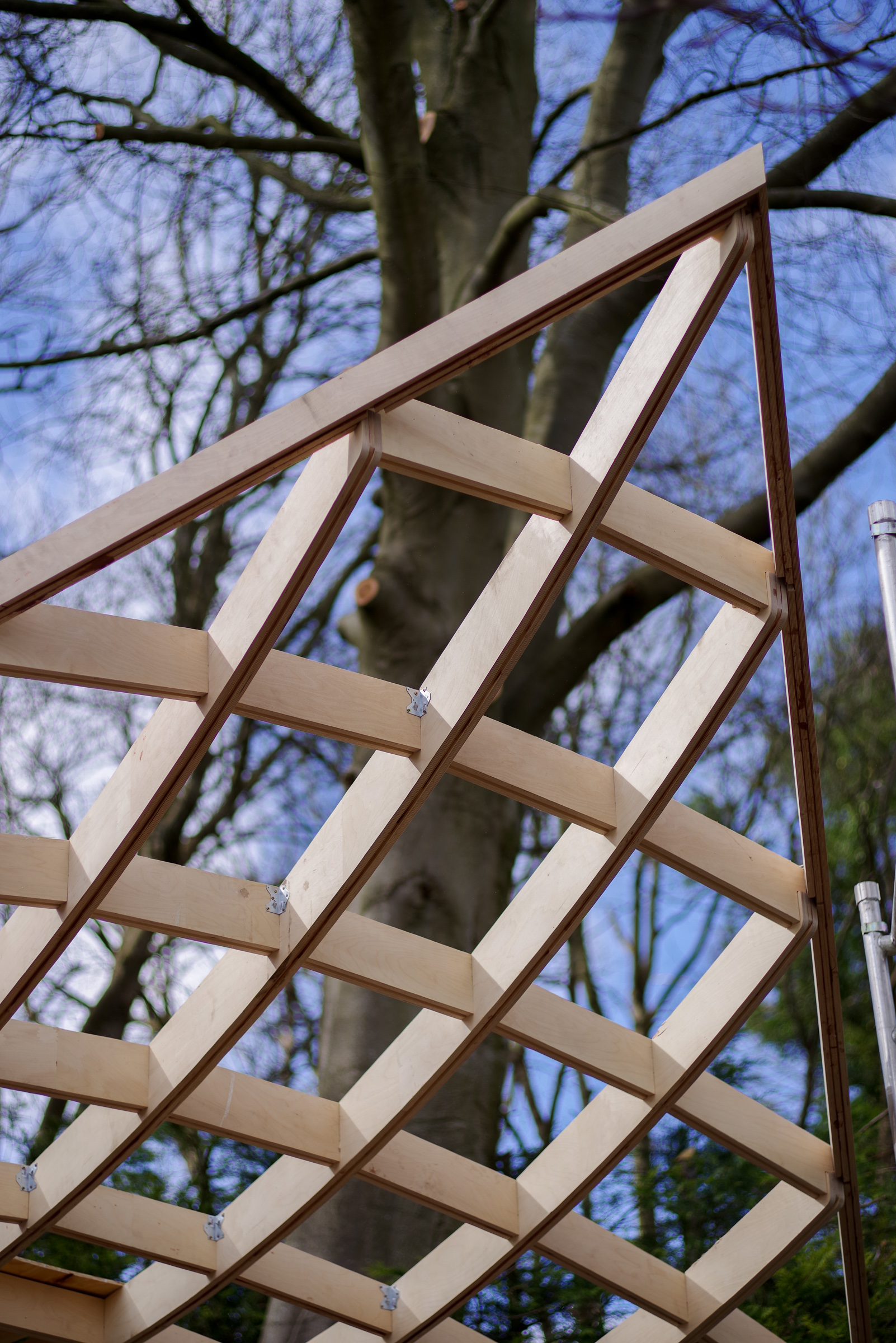
Bat Wing Studio is a home office and gym set into a hillside in the North Wessex Downs, an Area of Outstanding Natural Beauty in Berkshire. Its roof rises at the front to frame the view across the valley and swoops down at the back into the trees. Inside, a lattice of curved birch plywood beams spreads across the ceiling like the veins on the underside of a bat’s wing.
It is a building that could not have been made any other way. Every one of those beams was drawn in 3D on a computer and cut out by machine. This is the story of what that made possible.

The problem
The form came from the site. Rotating the studio 45 degrees to the slope turned the doors towards the view, and left the building with two high corners and two low ones. Drawing lines diagonally between them creates a saddle shape, or hyperbolic paraboloid: a roof that curves up in one direction and down in the other.
Saddle roofs are rare because they are hard to build. Most are concrete shells, which need wasteful timber formwork and end up thick, heavy and cold. Timber versions have usually relied on deep edge beams, or on steel cables tying the corners together. I wanted none of that: a light timber roof sitting on just three points, sailing above a continuous band of glass, with no visible steel and no ties.
What designing for CNC means
CNC stands for computer numerical control. A CNC router is a cutting machine guided directly by a drawing. Instead of a carpenter measuring and cutting each piece by hand, the machine cuts exactly what the architect has drawn, to within a fraction of a millimetre.
The important consequence is this: a curved part costs almost no more to cut than a straight one. Once you are designing for the machine, complex geometry is no longer expensive, and the design is freed from the constraints of standard timber sizes and hand-cut joints.
It also changes the architect’s role. Normally, drawings describe what should be built, and a contractor interprets them on site. With CNC, the drawing is the instruction to the machine. I had direct, millimetre control over the finished building. In many ways it is like designing a very large piece of custom furniture.


How it worked
I modelled the whole roof structure in 3D. The beams form a grid of curves running diagonally across the roof. The longest and most curved beam runs from the back corner and cantilevers up to the highest point at the front. Beams running front to back are deeper than those running side to side, accentuating the upward “whoosh” of the roof.
Each beam is made of three staggered layers of birch plywood: two outer layers of 18mm and a 12mm core. On the underside, the core is set back to leave a groove along each beam, making it look lighter. At the three supports, the beams slot onto a 12mm steel armature in place of that central layer, so the steel disappears inside the timber.
From the 3D model, I flattened every component into 2D outlines and split them into pieces that would fit the machine. That produced 141 unique parts, nested onto 18 standard sheets of plywood (1.2 × 2.4m). I sent the outlines to Oban CNC as DWG files. They cut everything, materials included, for £2,750 plus VAT, which looks remarkably good value in hindsight. They turned the offcuts into a compost bin.

The team
Digital fabrication doesn’t remove the need for good people; it depends on them.
Webb Yates were the structural engineers. They guided the initial structural concept and, once I had drawn up the design, tested it in their own 3D model to confirm it would stand up and to check for weak points. They chose the glue, and specified concealed dowels between the layers so the pieces could never slip past each other over time. None of the dowels are visible.
Jack Chivers built it, and deserves great credit. Because Jack and I knew each other well, we could work informally and collaboratively, sharing 3D models rather than producing a conventional tender package. That saved the client a significant amount of my design time. Jack assembled the cut pieces into complete ribs in his workshop before bringing them to site, and because every part was machine-cut, the design came together on site exactly as intended.
What it makes possible
- Freedom of form. Curves, twists and one-off shapes cost little more than straight lines.
- Precision. Parts fit first time, and what’s built matches what was designed, to the millimetre.
- Off-site assembly. Components can be pre-assembled in a workshop, reducing time and disruption on site.
- Less waste. Parts are nested tightly on each sheet, and offcuts can be reused.
- Structure as finish. The beams that hold the roof up are the ceiling you see.
The trade-offs
It isn’t free of challenges. The design work happens up front, so the drawings have to be complete and correct before anything is cut. Every part must fit a standard sheet, which shapes how the structure is broken down. Weatherproofing still relies on conventional layers: here, a plywood deck, OSB and a glass-reinforced plastic roof covering. It also depends on a good fabricator and a builder comfortable working from 3D models.
Small buildings, made precisely
The client loves the studio and uses it every day as his home office.
The same approach suits many small buildings: garden studios, home offices, annexes, pavilions and outbuildings. These are projects where a single striking idea can be realised precisely and affordably, built in a workshop and assembled on site.


Thinking about a garden studio or small building? I’d be glad to talk it through. Get in touch
For the full design story, including the precedents behind the roof, read How I Designed the Bat Wing Studio, and see more photographs and information at the project page for the Bat Wing Studio.
Contact
Not sure where to start? Book an Old House Health Check
︎Contact Form
︎ info@tparsons.co.uk