We had been working on the design of an extension for the homeowner but work paused on the main house a bat survey being required for planning approval. Whist we were waiting for the bat survey the client asked us to look into designing a home office for them built into the hill above the main house.
The first design decision was to rotate the building forty five degrees to the slope so that the doors faced towards the view across the valley. Turning the building this way meant the slope would intersect with the building on the back two sides, sloping symmetrically upwards. We decided two slot windows running parallel to the ground would work well here, and to balance the form we decided the front corner should be higher like the back corner. This resulted in a form with two high corners and two low corners. Drawing straight lines between these points could result in a pitched roof if drawn with a central ridge, or if drawn diagonally across it would result in a saddle shape.
Saddle shaped roofs and other hyperbolic paraboloids are uncommon because the curved form is more complicated to achieve than a standard rectilinear form, but there are some key references I drew upon whilst developing the design.
The majority of solid saddle shaped roofs are constructed from concrete. A famous British example is Markham Moor petrol station canopy. There are other similar but more complex forms achieved abroad by Felix Candella and others. Constructing a concrete shell structure involves creating a timber formwork and pouring or spraying concrete onto reinforcement bars and then removing the formwork once the concrete has set. I was keen to avoid this approach due to the waste created in the formwork. Another reason for avoiding concrete for the roof was that it would need to be relatively thick for it’s size to achieve a minimum thickness of cover over the reinforcement bars and would look clunky as a result.
There have been a few timber saddle shaped roofs in the past. The most impressively expressive of these is The Waikikian, a restaurant in Hawaii. This roof relied on a perimeter beam and bent planks running crisscross to create a lattice like cross laminated timber shell. This shell structure relies on the tension being maintained from corner to corner. On the Waikikian there was a cable tied between the top two points to maintain the form, and this is something I was very keen to avoid. Another similar but much flatter roof structure was employed by Eduardo Catalano in a 1950s house in Raleigh, North Carolina. This had thick steel edge beams and a thick concrete slab base to maintain the tension across the form.
Neither of these approaches seemed ideal for the design of our roof. I was keen to avoid a thick edge beam on our roof as it would make the whole structure feel more heavy /oppressive inside. Ties between the upper and lower points of the structure would need to be avoided, and we were keen to work in wood, not concrete or tensile fabric. We wanted the structure to sit on only three points, at the two low corners and at the back top corner. It would cantilever over slot windows running the whole way around.
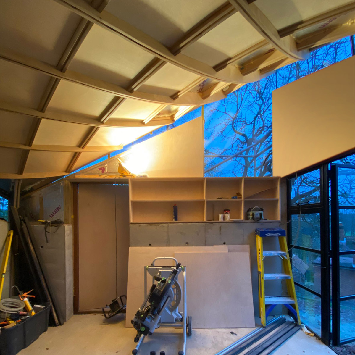
Rather than run straight beams across the form, my design was to create a grid of curved beams running diagonally across. The first beam forms an arch between the two lower corners and supports the longest and most curved beam running from the back corner and cantilevering up to the highest point at the front of the building. I decided it could become an attractive feature to expose the structure on the underside of the roof. I designed the beams running front to back to be deeper and lower than the ones running side to side to accentuate the upwards ‘whoosh’ of the roof form.
Each of the beams was custom cut from three staggered layers of birch ply. Each piece was drawn in exhaustive detail in the computer and cut out using a computer numerically controlled router. There were two outer layers of eighteen millimetres thick with a central piece twelve millimetres thick, laminated together with dowels to prevent the pieces slipping relative to each other. The visible underside of each beam had the twelve millimetre piece recessed so that each beam had a groove along its centreline and appeared ‘lighter’. A relatively small edge beam runs around the exterior and is hidden by overlapping ceiling panels.
A steel armature attaches the three low corners of the structure down onto a cast-in-situ concrete retaining wall. Constructed from twelve millimetre thick steel, the beams slot onto this in place of the central twelve millimetre plywood layer. The bolts, other connecting metalwork and insulation is concealed behind thin 6mm plywood ceiling panels. Two layers of nine millimetre plywood was glued and screwed to the top of the beams to form the roof deck. On top of this a layer of oriented strand board (OSB) was attached along with a protruding edge ‘lip’. A glass reinforced plastic (GRP) roof covering provides the waterproofing to the roof.
Frameless glass windows run around the perimeter at high level bedded into simple aluminium angle extrusion and allowing the roof to sail above the walls with no connection. A crittal framed pair of doors forms the front of the building, surrounded by charred timber cladding.